Water Well Pump Wiring Diagram
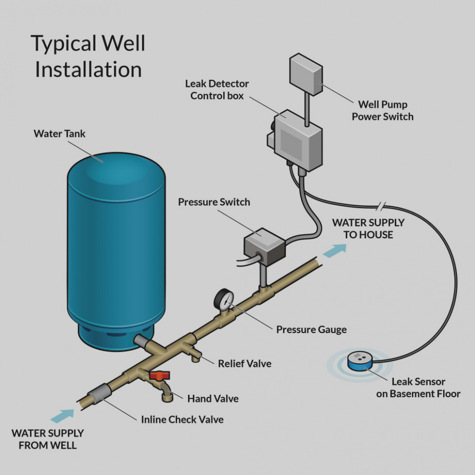
For the water to enter your house however you should also have your own pump. This article describes and identifies the switches, controls, and safety devices used on water tanks and water pumps such as the pump pressure control switch, pump motor relays, water tank relief valve, water tank pressure gauge, water tank air volume control, and water tank air valve.
Well Pump Wiring Diagram — UNTPIKAPPS

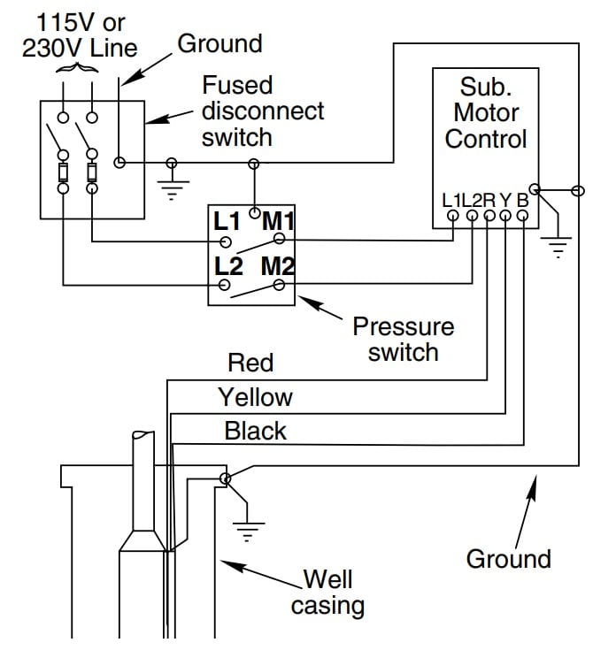
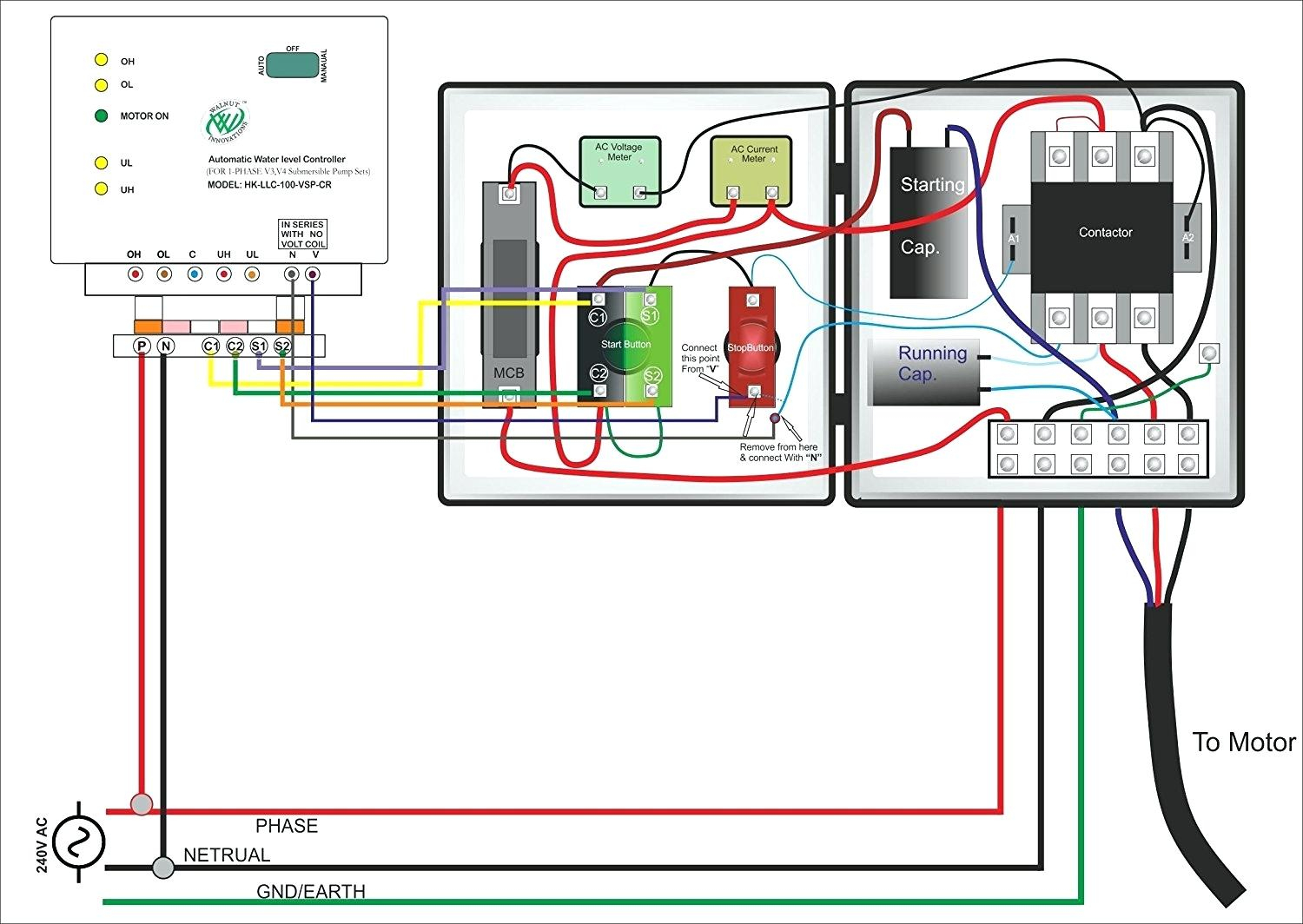
Submersible pump control box wiring diagram for 3 wire single phase.

Water well pump wiring diagram. Jul 02, · grundfos pumps are carefully inspected and tested before shipment. Tank tee connets water line from pump to pressure tank and service line from tank to house. There are just two things that will be present in any 2 wire submersible well pump wiring diagram.
Assortment of submersible pump control box wiring diagram. Circuitry layouts are made up of 2 points: Failure to install in compliance with local and national codes and.
How to wire a square d™ power pressure switch. Single phase 3 wire submersible pump control box wiring diagram. Many well drillers are not licensed and finding a licensed electrician can add unnecessary time and costs to the job.
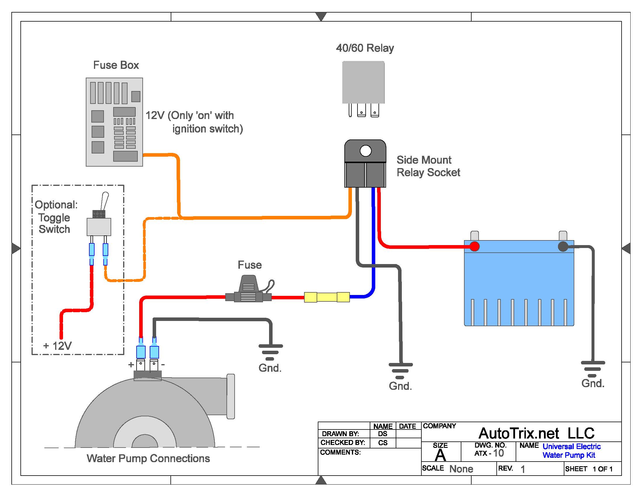
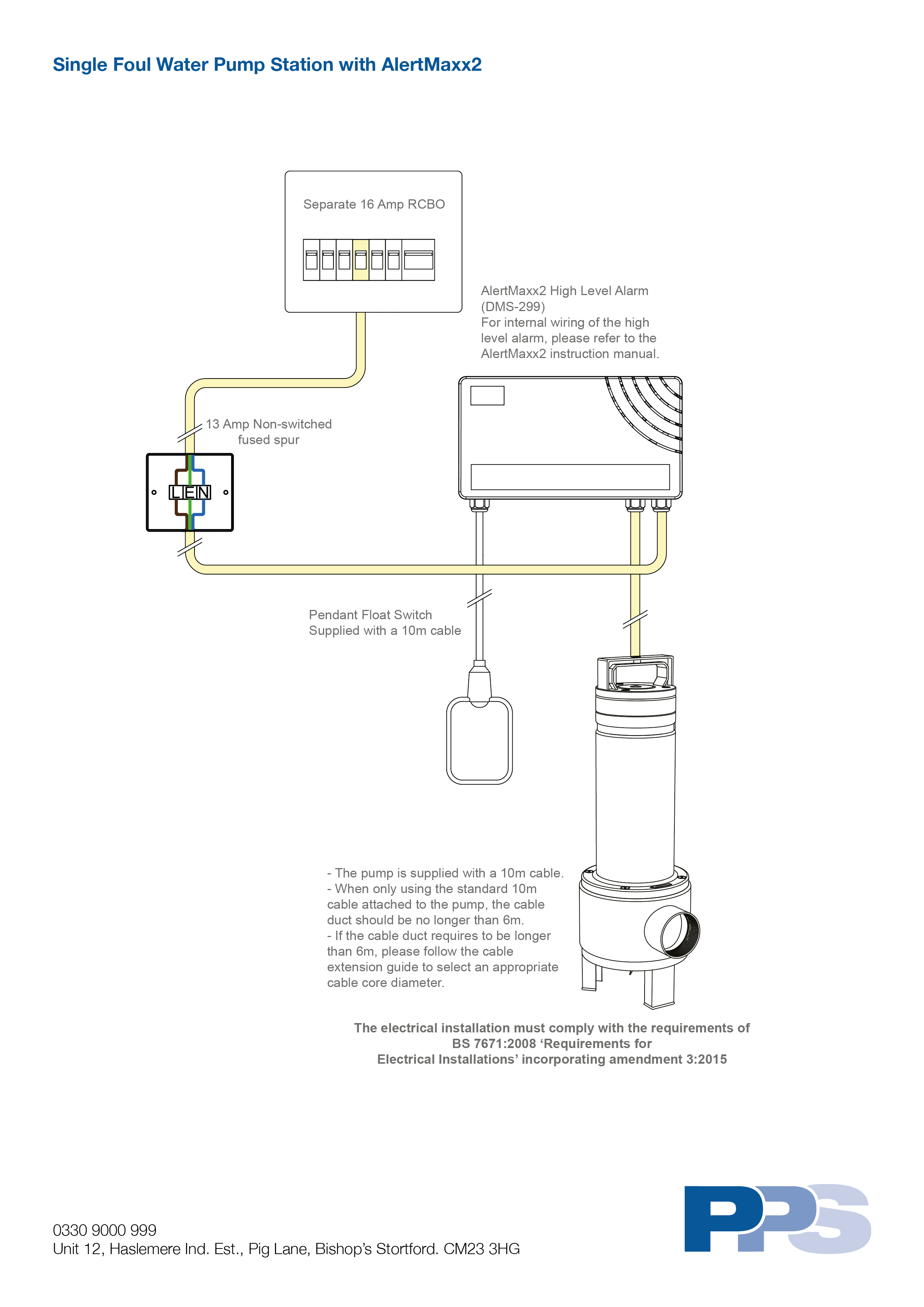
Wiring diagram also gives useful suggestions for tasks which may need some extra gear. A float switch is a mechanical switch that floats on top of a liquid surface. The information provided here is for educational purposes only.
Check valve installed near the tank inlet to hold water in the tank during pump installation when the pump is idle. A wiring diagram is a kind of schematic which uses abstract pictorial signs to show all the interconnections of elements in a system. The first component is emblem that indicate electrical component from the circuit.
A double pole switch is the safest way to make sure that both lines of the 240 volt circuit power to the pump are turned off. Injunction of two wires is generally indicated by black dot at the junction of two lines. Well pump & water pump controls:
Wiring diagram for 220 volt submersible pump submersible pump 1993 ford mustang wiring diagram 2001 ford mus submersible pump submersible well pump sump pump. Water pump wiring troubleshooting well installation wire a three 120v how to 220 pressure switch terry love control install and replacement on sanborn 110 float submersible diagrams square d 40 60 psi plastic exterior tameson com i am rewiring can you help auto restart v table level controller circuit using pumps an overview 3 vs 4 catalogue. Float switch connection auto manual single phase water pump youtube electrical circuit diagram electrical projects water pumps.
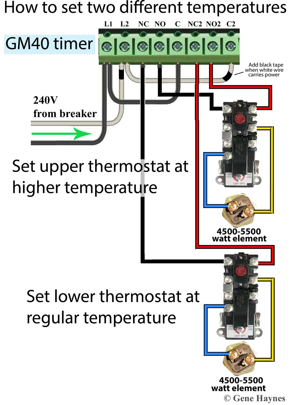
When looking directly at the switch you should see four terminals going from left to right. A circuit is usually composed by many components. All motors have a wiring diagram on the motor label;.
With this sort of an illustrative guide, you’ll have the ability to troubleshoot, stop, and full your projects without difficulty. Green = ground blue = run brown = start black = common you will see that For more information about 220 volt wiring diagram 220 volt wiring diagram.
It will be able to supply you with additional. I have attached an image of the correct wiring. As the liquid level goes up or down, it moves vertically with the liquid level.
It shows the elements of the circuit as simplified forms and also the power as well as signal links between the devices. How to install and wire a well pump everbilt 3 4 hp submersible water wiring troubleshooting 110volt electrical 2 motor 10 gpm three 120v wires cut diagrams vs thin 5 franklin electric 1hp 40ft deep potable flotec model fp3212 02 run goulds control box for 3hp 110 float switch 220 6 lessons direct motors maintenance. Symbols that represent the elements in the circuit, and lines…
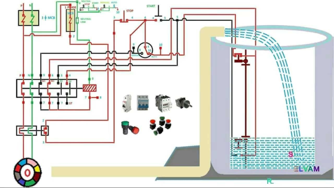
Technically qualified personnel should install pumps and motors. This book even contains ideas for extra supplies that you might need to be able to end your assignments. From that depth, clean water is transferred via a pipeline constructed above the ground to a large reservoir tank at the top of steel made supporting structure in the form of a tower.
As stated earlier, the traces in a 240 volt well pump wiring diagram represents wires. Another thing you will discover a circuit diagram could be traces. Float switch wiring automatic manual single phase water pump controller water pump youtube electrical circuit diagram water level switch water pumps.
A wiring diagram is a kind of schematic which uses abstract pictorial symbols to show all the interconnections of components inside a system. To wire up a pump in a water well is a relatively small project you can do yourself (assuming you are the homeowner and local codes allow for this). Water pump wiring troubleshooting repair diagrams.
However, it doesn’t imply connection between the cables. 3 wire well pump diagrams are more complicated and require a better. Sometimes, the cables will cross.
We recommend that a licensed contractor install all new systems and replace existing pumps and motors. 44 luxury single phase submersible pump starter. Single phase submersible pump starter wiring diagram on water control panel inside to.
Black wires go to black wires and the green wire the ground goes to the ground wire. Wiring a water well pump controller and switch: Water well pump wiring diagram download.
Water pump wiring diagram single phase. Place the heat shrink tubing over the. There’ll be principal lines which are represented by l1, l2, l3, and so on.
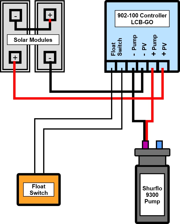
Shurflo 9300 wiring diagram for pumping into a pressurized tank submersible well pump well pump water pumps. Shallow well adapter built into the casing, which eliminates the need for a separate shallow well. Wiring diagram and troubleshooting the soft starter for potable water well pump well pump is installed underground, on the bottom of vertical, narrow, about 30 meters long pipe.
To ensure maximum performance and reliability, please follow the simple instructions in this manual. Designed for homes, cottages, and booster services. Taps are provided to accept.
Deep submersible well pumps will be either 2 wire or 3 wire well pumps and 3 wire well pumps will need a separately installed control box.
2 Wire Submersible Well Pump Wiring Diagram Wiring

220 Well Pump Wiring Diagram Wiring Diagram
12 Awesome Wiring Diagram For 220 Volt Submersible Pump

[DIAGRAM in Pictures Database] Electric Water Pump Wiring
Wiring Diagram For Water Pump Wiring Diagram Schemas
27 Water Pump Installation Diagram Wiring Diagram List

Grundfos Submersible Pump Wiring Diagram Wiring Schema

Water Pressure Tank Installation Diagram — UNTPIKAPPS

Square D Well Pump Pressure Switch Wiring Diagram

Well Pump Pressure Switch Wiring Diagram Wiring Diagram
Beauchamp Water Treatment Blogspot Submersible Well Diagrams

29 Water Well Pump Wiring Diagram Free Wiring Diagram Source
Submersible Well Pump Wiring Diagram Wiring Diagram
3 Wire Submersible Pump Wiring Diagram Wiring Diagram
32 Well Pump System Diagram Wiring Diagram Database
Submersible Pump Installation Diagram Hanenhuusholli
Water Pump Wiring Troubleshooting & Repair

Beauchamp Water Treatment Blogspot Submersible Well Diagrams

Gallery Of Submersible Well Pump Wiring Diagram Sample
