Crankshaft Position Sensor Wiring Diagram
Crankshaft position sensor wire diagram. 18.11.2015 · if spikes or glitches are observed, carefully wiggle the wiring harness and connector for the sensor in question to try and determine whether the problem is a loose connection or a defective.
Repair Guides Electronic Engine Controls Crankshaft Position (ckp) Sensor

Where is a crank shaft sensor located at on a 94 chevy s10 b diy forums.
Crankshaft position sensor wiring diagram. This crankshaft position sensor is strongly engineered to reach the oe parts specifications, ensuring precise. P0335 nissan description the crankshaft position sensor also known as the crank position sensor is an electronic device used in an engine to record the rate at which the crankshaft is spinning this information is used by the electronic control module to control ignition and fuel injection the sensor system consists of a rotating part typically a disc as well as a. First off click wiring diagrams not tsb's.
Each component ought to be placed and linked to different parts in particular way. The scan tool can display the crank position sensing decode mode. 2001 chevy silverado 1500 5 3 i need a wire diagram for the crank.
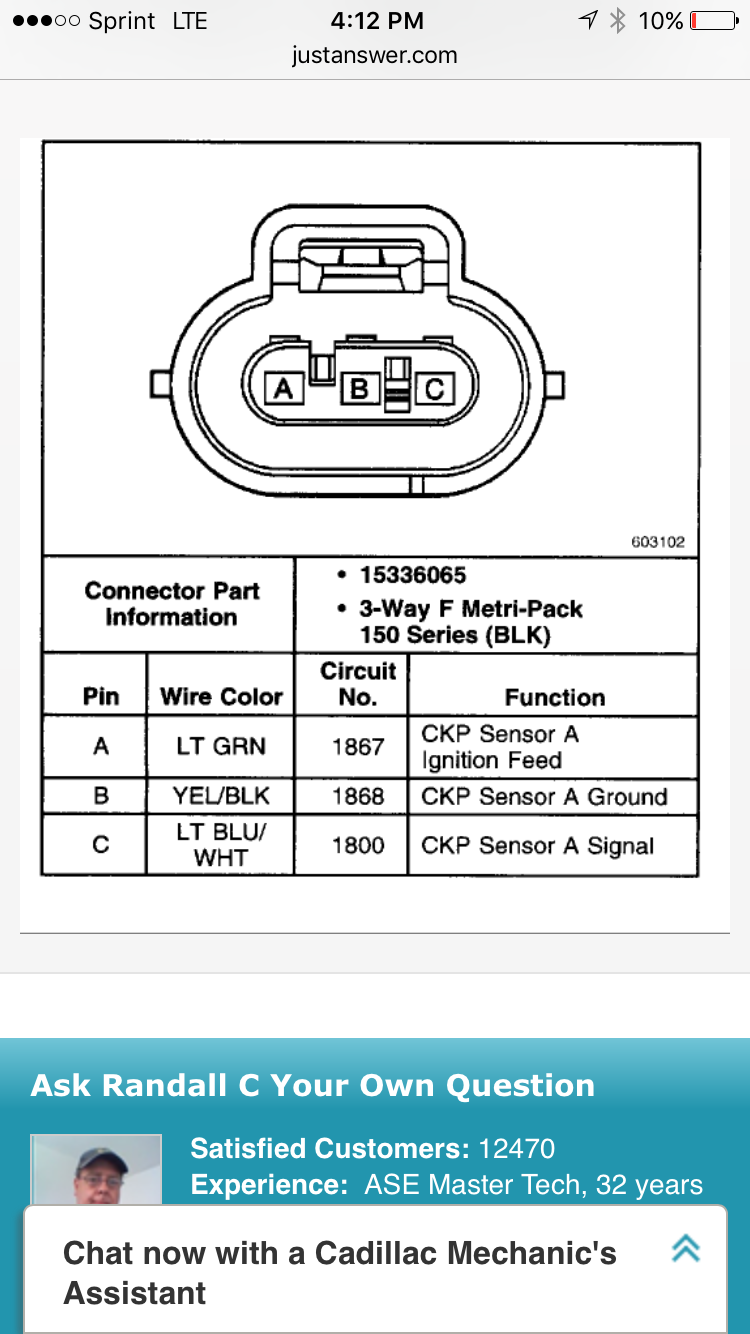
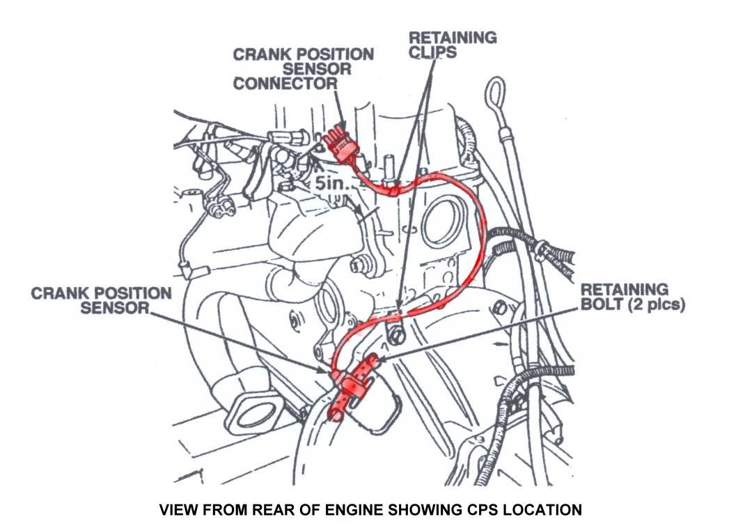
The crankshaft position (ckp) sensor is located on the right lower side of the engine and above the starter motor. The amount of wires in their connector (of course there’s always an exception to every rule). Diagram chevy 5 7 vortec crank sensor wiring diagram full version.
Hello, this is the wiring diagram for the crank sensor circuit. 3 wire crank sensor wiring diagram vortec wiring diagram faint repeat9 klictravel nl. Scroll down to the third diagram.
To measure the spinning resistance of the crankshaft sensor use an ohmmeter (multimeter). Written in an easy to use, friendly style; Properly functioning sensor will range from 550 to 750 ohms.
By continuing to use this site you consent to the use of cookies on your device as described in our cookie policy unless you have disabled them. Pink is fused battery, yellow is sensor signal and purple is sensor ground. Did the wires get ripped out of the sensor connector at the sensor?
Joined jan 2, 2020 · 18 posts. Ignition system circuit diagram 1996 1999 chevy gmc pick up and suv. Clicking this will make more experts see the question and we will remind you when it gets answered.
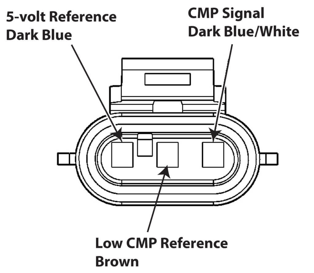
Schematics and diagrams gmc crankshaft position ckp sensor replacing. The second is the signal wire through which the camshaft position sensor sends its voltage to the ecu. Delphi crankshaft position sensor is created to monitor the speed and position of a crankshaft.
Discussion starter · #1 · jan 11, 2020. The following tutorial will help you to test the camshaft position (cmp) sensor: Solved crank sensor coil pack computer wiring diagram fixya.
Accelerator pedal position sensor wiring diagram wiring diagram is a simplified satisfactory pictorial representation of an electrical circuit it shows the components of the circuit as simplified shapes and the skill and signal links amongst the devices. If it's replaced, you'll need to have the crankshaft position sensor relearn procedure done with a scan tool that is capable. Wiring diagram september 09, 2020 03:37.
And applies equally to eunos roadster (japanese market model) and mazda miata (us market model). Both wires are connected to the car computer (ecu). Testing the ignition system is a breeze.
Save on delphi engine camshaft position sensor ss at advance auto parts. Other sensors tap into the reference voltage. Pink is fused battery, yellow is sensor signal and purple is sensor ground.
This sensor measures the pressure of the engine oil and relays this data to the pcm. The second is the ground wire, which is necessary for the current to complete an electrical circuit. Covers all aspects of maintenance and repair;
Crankshaft sensor diagnosis with an ohmmeter. It shows the components of the circuit as simplified shapes, and the faculty and signal connections in the. Are you planning on replacing the sensor or just try to fix the wiring?
Does anyone know what the wires are supposed to be when reading with a volt meter? Now in case you’re wondering what i mean by two and three wire types… i’m referring to; Under system click on engine ,then under subsystem click on fuel controls.
Click the search button then the blue link. 14 flexplate jet 5 7 starters 0170 000 starter. The crankshaft sensor receives reference power and ground from the pcm.
This typical circuit diagram of the ignition coil, ignition control module, camshaft and crankshaft position sensors applies to the 1996, 1997, 1998, 1999 chevrolet/gmc 1500, 2500, and 3500 pick ups equipped with a 4.3l v6, or a 5.0l v8, or a 5.8l v8 engine. In the absence of any problems, you can move on to finding hidden issues in the wiring diagram of the device. Crankshaft position sensor wiring diagram 1999 4.3l 4x4.
We collect plenty of pictures about 2003 dodge ram 2500 57 hemi throttle body wiring diagram.
schematics and diagrams GMC Crankshaft Position (CKP) Sensor Replacing?

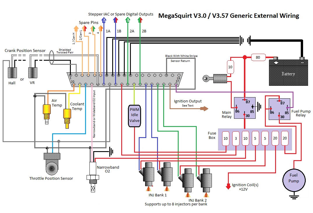
MS3 crank position sensor wiring Miata Turbo Forum Boost cars, acquire cats.
Crankshaft Position Sensor Connector Wiring Crank by Design
Crankshaft position sensor connectors GM Forum Buick, Cadillac, Olds, GMC & Pontiac chat
P0335 stalling Chevrolet Tahoe — Ricks Free Auto Repair Advice Ricks Free Auto Repair Advice
Wiring for upper crankshaft position sensor connector

Delphi Crankshaft And Camshaft Position Sensor Wiring Diagram

Repair Guides Electronic Engine Controls Crankshaft Position Sensor (ckps)

Jeep Cherokee Engines Camshaft Position Sensor / Sync Pulse (Stator) Diagnostics
Honda Wiring Diagram Crankshaft position sensor, Diagram, Circuit diagram

2002 Gmc Sonoma 4.3 Crank Sensor Wiring Diagram

Cam Sensor Wiring Diagram
DTC P0335 Crankshaft Position (CKP) Sensor Circuit
Repair Guides Electronic Engine Controls Crankshaft Position (ckp) Sensor

Repair Guides Electronic Engine Controls Crankshaft Position (ckp) Sensor

2002 Dodge Stratus 2.4l Wiring Diagram Crankshaft Position Sensor
Crankshaft position sensor configuration and conditioning circuit. [... Download Scientific

Delphi Crankshaft And Camshaft Position Sensor Wiring Diagram

Repair Guides Electronic Engine Controls Crankshaft Position Sensor (ckps)
